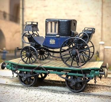
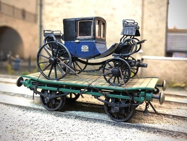
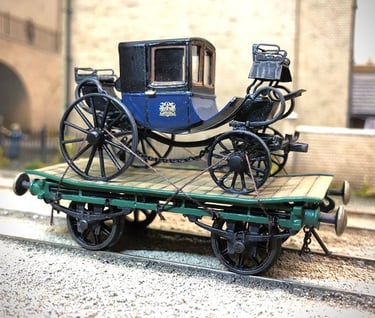
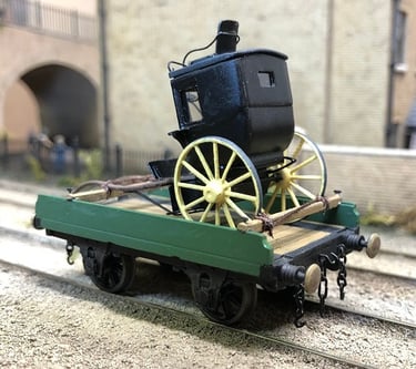
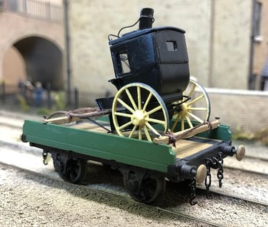
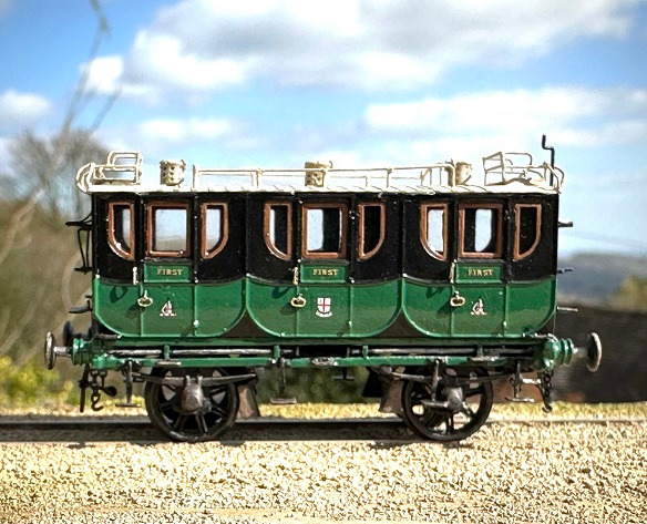
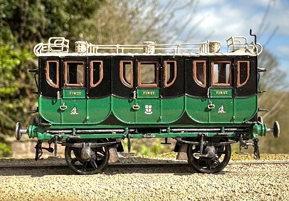
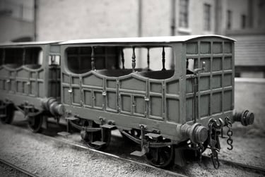
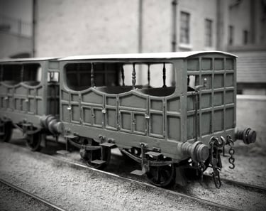
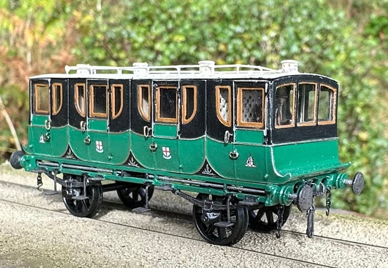
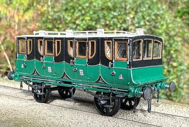
First Class Carriages for Coventry
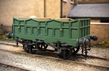
The First class carriages for Coventry consist of cast solebars and headstock, buffers, buffing springs and brakes whilst the body, roof and detailing are etched brass. This mixed media approach seems to suit the carriages well, the etched sides, ends and roof providing uniformity whilst being light enough to enable several to be pulled by one Bury 2-2-0. For abit of ballast to keep them on the rails the underframes are cast, and the combination seems to be just about the right weight.
Each solebar or underframe side is cast as one piece to include upper and lower frame bars, axleguards, springs and buffer rods. This results in a useful casting which saves time in construction however, it is complicated and seldom casts well. In hindsight it would be better not to include the buffer rods but make provision for these to be added afterwards using 0.7mm brass rod. The headstocks or buffer beams are also cast, one with a brake bracket and one without for the other end although this casting is required for both ends if the carriage is unbraked as many of the Firsts were.
There is much cleaning up of the castings to do before soldering and the buffing springs must be included in the assembly as they are captive between the solebars. In fact, it became apparent after I had built a couple of underframes that the buffing springs can be used as a useful spacer to ensure the frames are the correct width apart and benefitted from being soldered in place before the headstocks were added at either end. At this point one must decide if the carriage is braked or not and the correct headstock fitted at either end together with a small casting for the brake gear if required. The brake blocks themselves are glued together as pairs on a transverse rod of brass wire but need to be painted and set aside to be fixed in place right at the end after the wheels have been fitted.
Once the underframe assembly is complete, the etched steps can be folded up and soldered in place. This is straightforward enough but very time consuming as there are fourteen to fit, two per door and two more for the guard or brakesman. Four lower end steps are also fitted at this stage as it’s easier to do it now than after the body is secured to the frames. Coupling hooks and side chains are also assembled and fitted together with four buffers which always benefit from a little cleaning up in a drill chuck with a little emery block. These carriages are so tiny that proprietary 3-link couplings are a bit too large and leave an unrealistic chasm between the buffer heads under tension, so I fit my own home-brewed screw coupling which ensures the most reasonable spacing between buffer heads. The frames still require wheels, but I prefer to do this after painting as they get in the way otherwise.
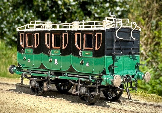
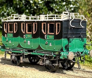
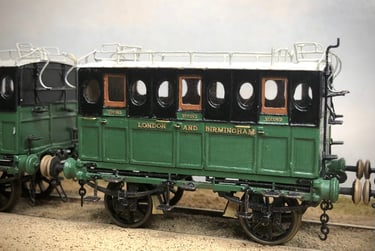
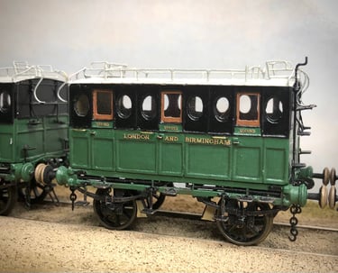
The body of the First is from an etched sheet consisting of two sides, two window backing pieces (of which more later), two ends, partitions, droplight frames, roof and myriad other details such as roof seats, steps, commode handles, door handles and so on. The two sides benefit from annealing before lying them face down on a foam mat and gently rolling the lower half with a wooden dowel. This results in a gentle curve or turn under to the lower body side to match the profile of the ends. The inner face needs to be cleaned with emery paper as the annealing process can leave a coating which the solder doesn’t seem to like. The window backing piece is then soldered in place ensuring the inner frames line up precisely with the body side apertures. The drop light frames can also be added at this point whilst access is easy and tiny hinges for the lower third of the door as well.
It is tempting to assemble the body by adding the ends now however, I found that the subsequent positioning of the large end footboard is quite difficult as the body has to be propped up end-on which doesn’t make life easy. Therefore, securing the footboards in place before assembling the body is recommended. The height of the footboard is best determined by the length of the legs of the guard/brakesman when seated less about 1mm to take into account the thickness of both roof and seat. Once the two footboards are fitted with their distinctive vertical brackets, the body can be put together soldering the ends inside the edge of the sides. These are followed by the partitions and ensuring everything is square at this stage is critical, it’s very difficult to correct if it isn’t spot on.
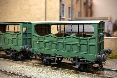
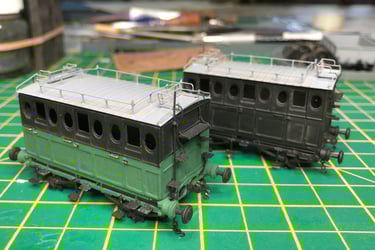
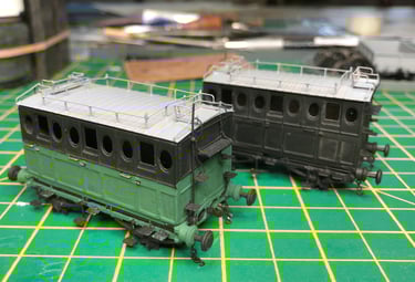
The whole A4 sized fret for these firsts, as it comes from the etchers, contains enough for three carriages and the surrounding frame provides enough spare material for the floors which is very handy. So, a floor is cut, soldered in place and the spare material stashed in the scraps box. The floor must be left about 1mm short at either end to allow for the upper curve of the headstock casting when the body and underframe are finally united. Four small steps are then added, one in each corner, neatly fitting into the slots provided in the bottom corners of the body side. The roof etch is annealed and rolled in the same way as the body side and once offered up to the body to check the curve matches the end profile, the luggage rails can be soldered in place. This is done by poking a piece of 0.3mm brass wire down through the hole provided in the etch, soldered underneath and trimming it a little over length on top. This process must then be repeated for every upright post leaving the corner posts a little longer. Once they’re all in place the horizontal rails can be added and at this point the upright posts can be snipped to their correct length. Unfortunately, the process is tedious and fiddly, but the end result is worth the effort. Two roof seats are then folded up and soldered in place taking care to see that they sit level which is not always obvious when the roof is still unattached. The curved corner handrails are bent up from 0.3mm wire and soldered in place from the roof corner to the front of the seat arm rest. These carriages had some very precarious looking steps between the lower steps and the footboard which seem to dangle on wrought iron legs. Although the etch provides for these I found them too delicate and bent up some 0.3mm wire as a substitute, soldering on the etched steps and fitting these to the underside of the footboard. The S curved handrails between the footboard and roof seat are similarly flimsy so these too were formed from wire and soldered to the footboard although left poking up at the top until the roof is finally fitted. Commode or grab handles are then fitted together with the door handles.
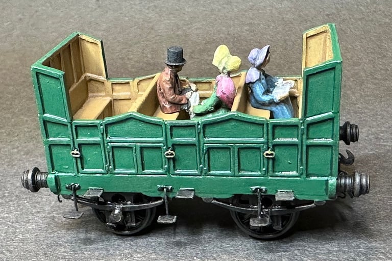
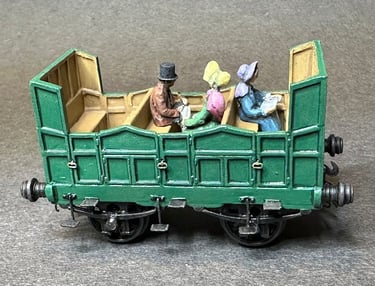
After all that, construction is essentially complete and the three sub-assemblies of underframes, body, and roof are given a good dip and brush in Carrs Acidip degreaser to remove or at least neutralise any solder flux residue. Once dry an even coat of etch primer from a Halfords rattle can transforms a sketchy looking model of tainted brass, dull metal and patches of solder into something more serious. This is followed by a similar coating of matt black. Each sub assembly is then painted to completion as handling is so much easier than after everything is stuck together, two coats of Humbrol 121 for the roof, green 76 for the lower body panels, for the window and droplight frames and for the buffer heads and brake shoes. In my modelling have always held to the rule that nothing should be finished in gloss varnish as it is simply too shiny for small models. However, I make an exception with these carriages as it is documented that they were kept in prime condition for the well-healed passenger and as such the finish on them would have matched the finestroad carriages which gleamed with several layers of varnish and pride. Two coats are applied, the first to provide a base for the tiny transfers applied using Micro-Sol to break down the carrier film, the second to protect the transfer and provide that polished finish.The carriage is glazed using clear acetate cut into appropriately sized rectangles and glued in place using 5-minute epoxy. I prefer this method as it allows for a bit of repositioning although if the glue is too close to the edge of the frame that’s not really an option. Afte glazing the roof can be glued on, again using the epoxy, the same goes for fixing the body to the underframe. At some point, usually whilst I’m waiting for a few windows to stick, I fit the bearings and wheels. First the area of axlebox that takes the bearing is cleaned up with a2mm broach and two long stainless-steel axles dropped in and the underframe placed on a Vee block. This identifies whether or not it is sitting square and level and provides an opportunity to fettle each axlebox until everything sits just right, then shoulderless pinpoint bearings are glued on one side, the wheels fitted, followed by the other bearings. The very last job is just to run round with a brush touching up areas where the glue might show and dry brushing the underframe with a little Humbrol 98.