No. 69 is finished!
Garnett's Double Coupe of 1839
10/24/20235 min read
I appreciate my last blog entry about the double coupé promised great things in the form of an explanation of the mould making and resin casting process for the seats. However, I forgot this almost as soon as I wrote it and subsequently have nothing to show for that process but, the model is complete and I can at least furnish a few photos of the finished article.
Many first (and some second) class carriages of the late 1830s had open solebars consisting of an upper and lower frame which allowed the long shafts of the buffers to reach right back towards the centre of the underframe where they pushed against large transverse leaf springs. These springs were paired with smaller springs connected to the draw hook at either end. One could argue that on such a small model this complicated arrangement of springs is not worth including as it can only be seen following a significant and unwelcome derailment when the carriage is lying on its side. However, the ends of the larger springs are visible against the buffer shafts, therefore I made a master from styrene so that the spring set could be cast as one unit to be fitted between the frames during assembly. A full train of first-class carriages was required for Coventry, so the spring set and a complete set of frames were produced as castings to speed up the duplication of all the common elements below floor level. Unfortunately, as previously mentioned, No.69 was longer than usual, and I found that my standard first underframe was much too short. Nor could it be ‘cut and shut’ like the etched body side as the step bracket plates and other details would be in the wrong position relative to the doors, the underframe would have to be built from scratch.
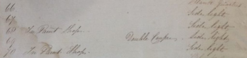
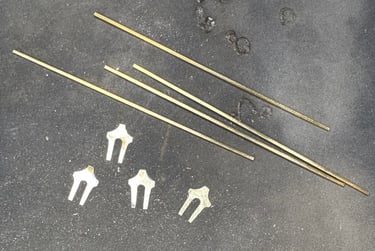
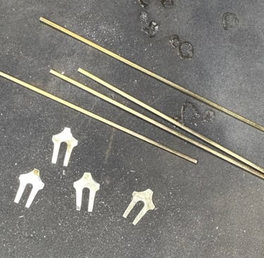
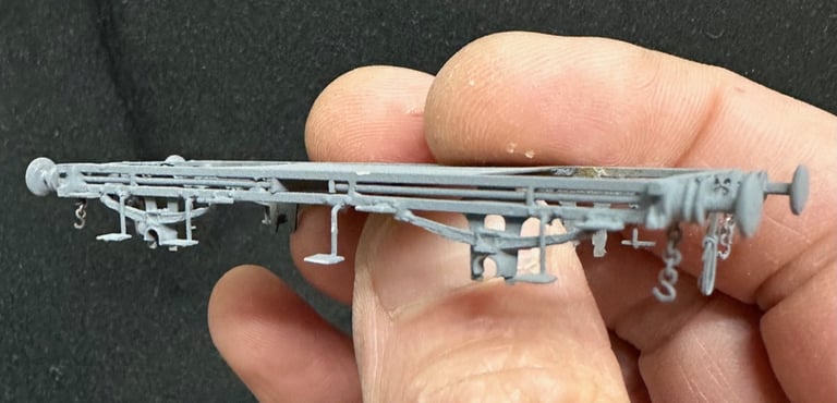
Fig.1. Four lengths of 1mm square brass rod were cut together with four axleguards cut and shaped from 10thou brass sheet. These were soldered together to form a pair of underframe sides.
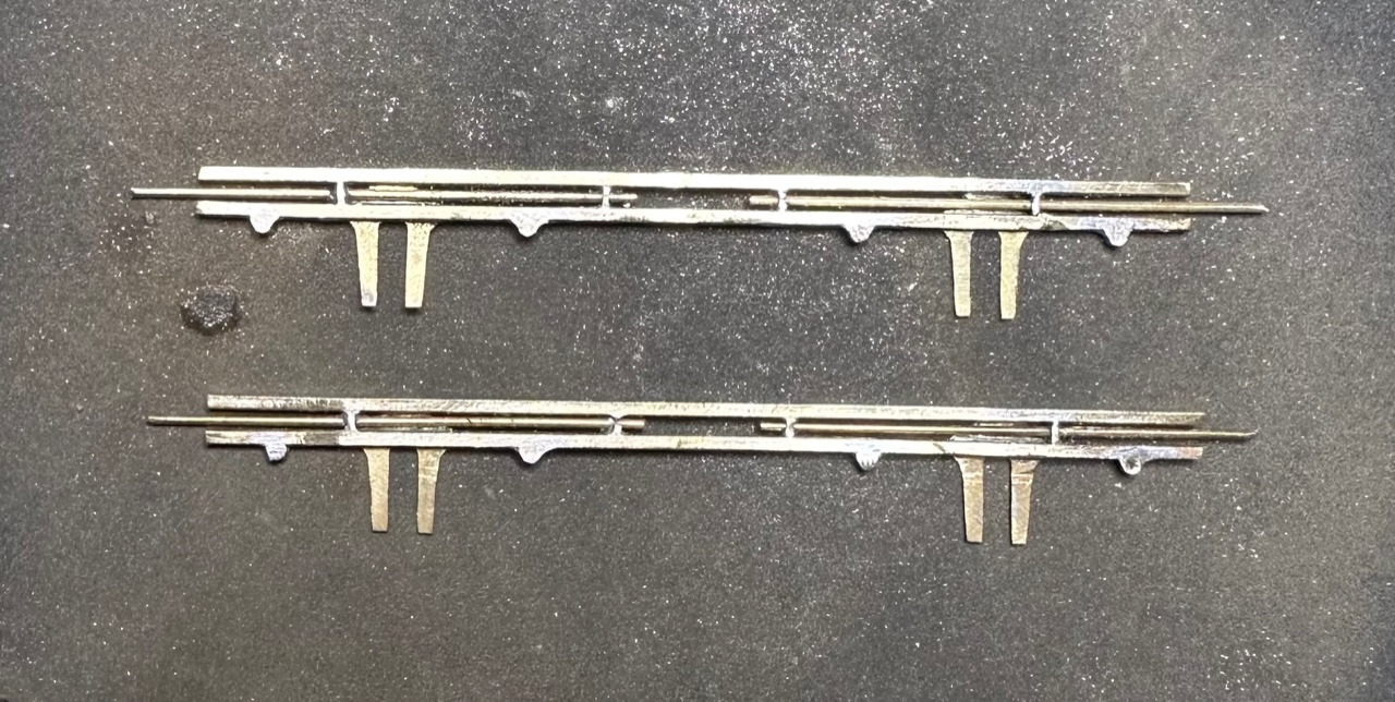
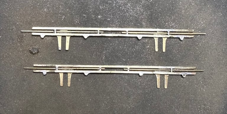
Fig.2. Guide plates for the buffer shafts were formed from 0.45mm wire bent and soldered in place before filing back flush, and 0.45mm nickel silver buffer rods were added. Roller boxes for the ends of the springs were cut from brass tube and soldered to the underside of the bottom frame.
A rummage through the scraps box uncovered some step bracket plates, originally part of a wagon detailing fret, which were soldered in place relative to the door positions. Steps were sourced from the same etch that provided the body sides and step hangers bent up from 0.45mm n/s wire before the frame sides were soldered to the headstocks to form the complete underframe. Only at this point did I realise that I had forgotten to include the spring casting I had taken so much trouble to produce. It could not be added now as the spring ends project between the frame sides making it about 3mm wider than the gap between the frames. Therefore, two curved strips of brass were soldered in to represent the springs and the carefully prepared spring casting was returned to the spares tray.
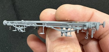
Fig.3. The completed frame sides were then soldered to a plate of 10thou brass to keep them parallel and create a sort of sub-floor for strength.
The buffers and distinctive pierced headstocks are castings prepared for the firsts, no modification necessary except to remember not to fit one with the brake gear casting to the left of the draw hook. Etched draw hooks and side chains were soldered in place, a pair of couplings fabricated, and the completed underframe given a good clean before etch priming followed by a coat of matt black.
Because these early carriages had such small axleboxes, I decided to represent them using just the pinpoint bearings, so these were glued in place with the wheelsets ensuring that all was level and running true. Not getting glue in the end of the bearing was not easy, and the first principle of ‘Sods Law’ dictates that one doesn’t find out if glue is in the bearing until it is set, and the wheels no longer go round! Note to self: always grease the ends of the axles before gluing the bearings in place.
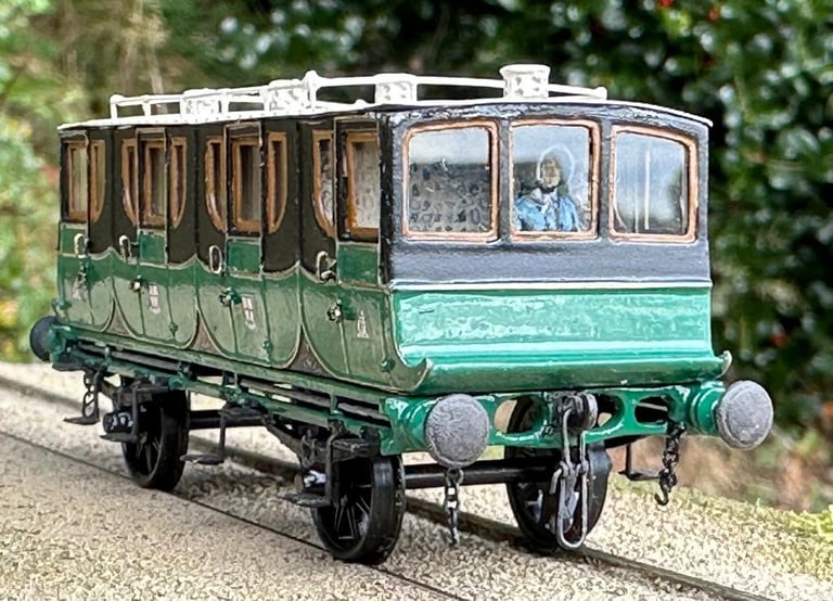
Fig.4. I chose to paint the body and apply transfers before uniting it with the underframe as it remains easier to handle as a separate unit.
Fig.5. The windows were glazed with clear styrene with the exception of the coupé ends which use microscope glass cover slips. I used these on the recommendation of fellow Shrewsbury Railway Modeller, Stephen Duffell, and I must say the finish is far better.
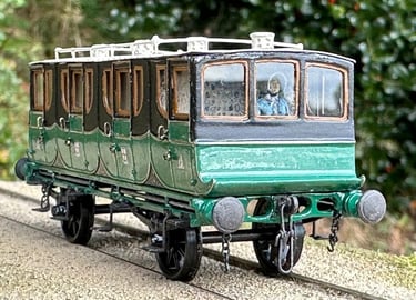
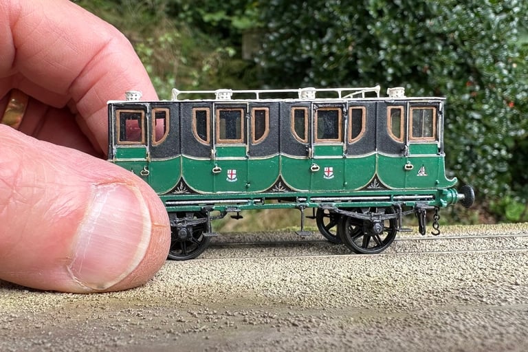
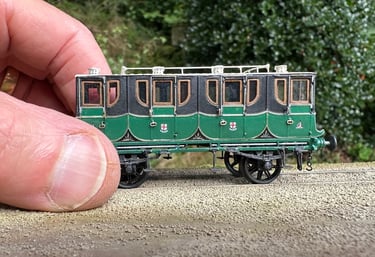
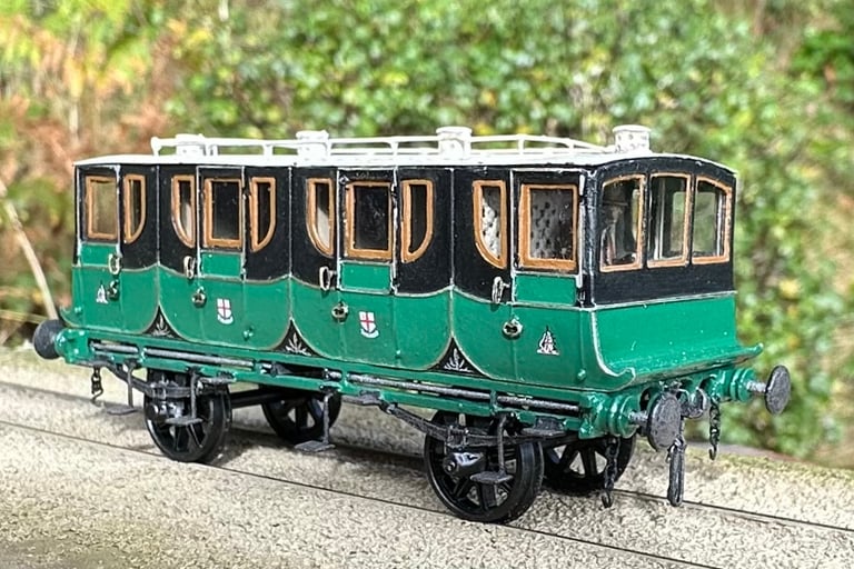
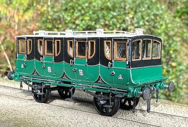
Fig.6. I hope that the final model is a reasonable representation of coupé No.69 of the London & Birmingham Railway.
Modelling a carriage for which there is no drawing, no photograph, scant reference in the 184-year-old minutes and a tiny artistic impression in the background of an illustration is certainly challenging, but we can fall back on what we know of contemporary practice, referencing dimensioned drawings and written specifications of the first class and Mail carriages which we are so lucky to have. Personally, I feel that modelling such obscure carriages is the best tool we have to bring them to life and help us understand how our beloved railways developed in the early years. I would like to record my thanks to Tom Nicholls for providing the historical and contextual information, a result of his unstinting and meticulous research without which I would be unable to create such models.